Upduino FPGA tutorial
Posted on by Idorobots
So, I've got my Upduino boards the other day and found out that the available docs are spread throughout the internet, the code examples don't work or are missing build instructions, and the official manufacturer-supplied tools require multiple hard to remember and follow steps. I figured there's got to be a better way, so I'm describing it here.
So you've got your Upduino. What now?
Upduino is a dream come true for my 8-years-ago self - a cheap FPGA capable of holding nontrivial CPU designs that you can program in an easy way. Like an Arduino. Get it? Upduino. Arduino. Almost as if it were on purpose.
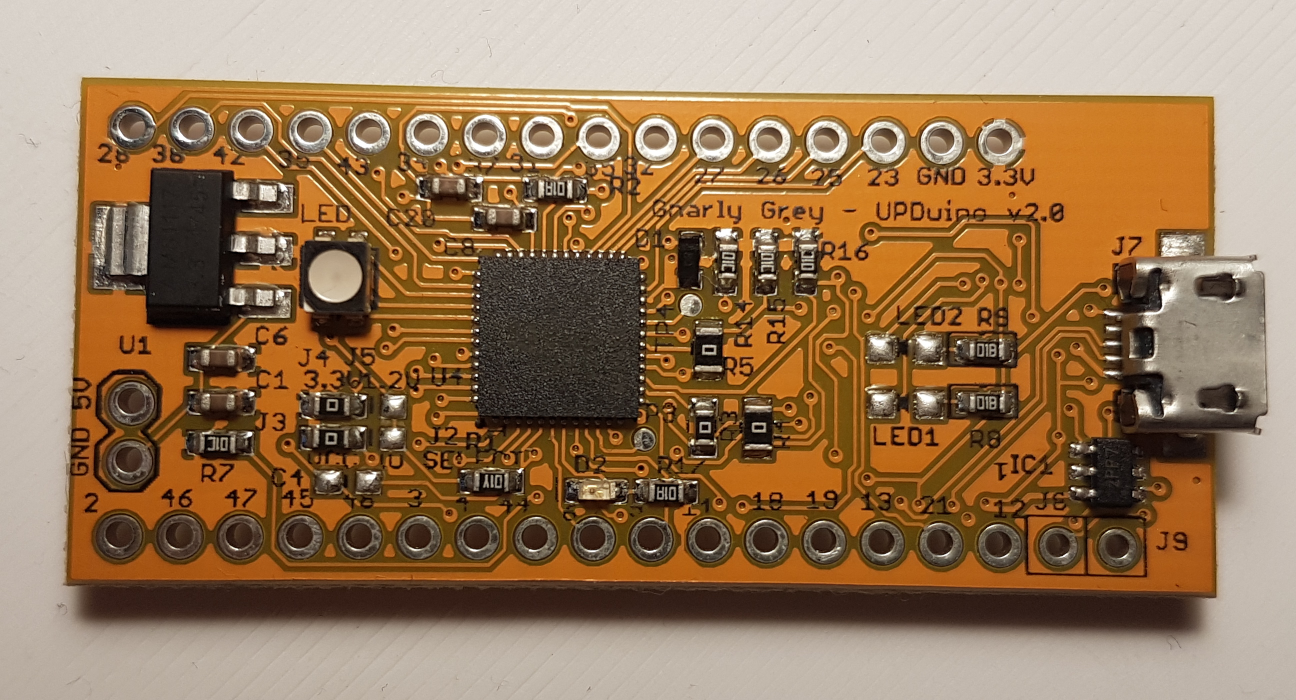
- a Lattice iCE40 UltraPlus FPGA - 5.3K LUTs, 1Mb SPRAM, 120Kb DPRAM, 8 Multipliers,
- 34 GPIO on 0.1 inch headers,
- SPI Flash,
- RGB LED,
- and 3.3V and 1.2V regulators.
In a nutshell, a great I/O capability and nothing-to-sneeze-at size for your designs, for the low, low price of 13.99 USD. What you won't get though, is an in-depth documentation with example programs showcasing all the features of the board. There is however the board schematic available and a simple Blinky project, that assumes an in-depth knowledge of the Lattice tool chain.
This tutorial will only use open source tools that you can conveniently run from the command line. If you're one of those people that prefer heavy UI-based solutions in the likes of Xilinx ISE, you probably want to follow this tutorial instead.
Environment setup
As already established, there are several options for programming your Upduino v2.0 board - some of them UI-heavy, others strictly command-line:- the manufacturer-supplied iCEcube2 - which, having prior experience with some Spartan 3 boards programmed using Xilinx ISE, I really want to stay away from,
- Project IceStorm - a fully open-source tool-chain for iCE40 family of FPGAs consisting of all the bits and pieces required in order to compile your Verilog designs, place-and-route them and upload them to the board (guess which one we're going to use),
- APIO - SIKE! We're going to use this one. Well, both actually...
APIO is a nice option if you're looking for an environment that is easy to setup and get going quickly, so that's what we're going to use in this tutorial. Install it using your favorite package manager, or PIP:
yaourt -Sy apio     # For Arch Linux.
pip install -U apio # When in doubt, you can install it this way.
...and then install all the required tools locally for APIO:
apio install system icestorm scons iverilog
That's it.
Blinky
To get you started we'll create a simple RBG blinky using APIO & Verilog. Project setup is very simple, just run the following commands:cd path/to/your/new/project
apio init -b upduino2 -p .
This will create an APIO project file in the path/to/your/new/project directory. Now we can add some source files starting with the package pin mappings (create a file named up5k.pcf and put the following I/O mapping in there):
set_io --warn-no-port led_blue 39
set_io --warn-no-port led_green 40
set_io --warn-no-port led_red 41
This lets our tool-chain know, that the led_blue, led_green and led_red signals should be mapped to iCE40 PFGA package pins 39, 40 and 41 respectively. Now for the actual source code (put it into blinky.v file):
module blinky (output wire led_blue,
               output wire led_green,
               output wire led_red);

   wire clk;
   SB_HFOSC inthosc(.CLKHFPU(1'b1), .CLKHFEN(1'b1), .CLKHF(clk));

   localparam N = 27;
   reg [N:0] counter;

   always @(posedge clk)
     counter <= counter + 1;

   assign led_blue = counter[N];
   assign led_green = counter[N-1];
   assign led_red = counter[N-2];
endmodule
The program defines a module called blinky that uses our three LED wires that we've mapped to the correct (trust me) pins of the chip package. The blinky module then proceeds to connect the clk signal to the internal high-frequency oscillator (line 6), which it then uses to define a very simple 27-bit counter called counter. On each positive edge transition of the clk signal (which is our internal, high-frequency oscillator, mind you) the counter will add 1 to its value. Lastly, the three most significant bits of the counter are then connected to blue, green and red LED signals respectively.
Upon execution we expect the counter to keep incrementing eventually changing the three most significant bits and, in turn, changing the three different LED colors.
Now is the time to connect your Upduino board to your laptop and program it:
apio verify # Verifies the correctness of the Verilog code.
apio build  # Compiles the code & prepares a bitstream ready for uploading.
apio upload # Uploads the bitstream to the board.
If everything went according to the plan, your Upduino will now start very slowly increasing its temperature until it reaches the temperature of a TOKAMAK fusion reactor and burns down your house. You. Are. Welcome.
Improved blinky
Obviously, the previous example isn't ideal - the LED is not current-limited resulting in the whole board getting uncomfortably warm to the touch. Also, if you are wondering about the SB_HFOSC thing in the code, and why it needs to be there, you are not alone, I was pretty confused as well when I tried piecing some working examples together. Let's tackle these problems one by one.
The SB_HFOSC is a Lattice-supplied module that is conveniently doing a lot of niceties for us - it connects the wire that we give it to the internal high-frequency oscillator, and the sixth line of the previous example just istantiates that module. Of course, there are more of these convenient pieces of code that are waiting for you to explore and re-use in your designs - it's like a standard library of sorts.
Among the depths of that file you'll likely find the SB_RGBA_DRV module, connecting three open-drain pins for the LED outputs, to the LED wires you pass it via the RGB# parameters. Sound rather well-suited for our purposes, especially the driver part - internally it modulates the power passed on to the LEDs using PWM. We can even adjust the current that the LEDs will be driven with! Given that knowledge, we can fix the other problem with the original blinky design:
module blinky (output wire led_blue,
               output wire led_green,
               output wire led_red);

   wire clk;
   SB_HFOSC inthosc(.CLKHFPU(1'b1), .CLKHFEN(1'b1), .CLKHF(clk));

   localparam N = 27;
   reg [N:0] counter;

   always @(posedge clk)
     counter <= counter + 1;

   SB_RGBA_DRV rgb (
     .RGBLEDEN (1'b1),
     .RGB0PWM  (counter[N]),
     .RGB1PWM  (counter[N-1]),
     .RGB2PWM  (counter[N-2]),
     .CURREN   (1'b1),
     .RGB0     (led_blue),
     .RGB1     (led_green),
     .RGB2     (led_red)
   );
   defparam rgb.CURRENT_MODE = "0b1";
   defparam rgb.RGB0_CURRENT = "0b000001";
   defparam rgb.RGB1_CURRENT = "0b000001";
   defparam rgb.RGB2_CURRENT = "0b000001";
endmodule
This time we're instantiating two modules - SB_HFOSC for the oscillator and SB_RGBA_DRV for the RGB LED driver. In order to switch the LEDS we're using the PWM-enable signals (RGB#PWM parameters) to turn them on and off according to the state of the counter. Additionally, we're configuring the "half-current" mode (setting the CURRENT_MODE parameter to 1) and setting the lowest possible current values (RGB#_CURRENT parameters), namely 2mA, per LED.
Running the code now should yield much better results:
apio verify
apio build
apio upload
The LED should now cycle through different colors without getting excessively hot in the process. That is, assuming that you didn't burn your house down by this point.
Other examples
This concludes the tutorial, hopefully it'll help you get started quickly with FPGA programming using the Upduino v2.0 board. The tutorial wouldn't be complete without some pointers to additional code examples, so here are a few:
- The original RGB Blinky supplied by Gnarly Gray
- A working Blinky, that I found very useful in figuring out how to run stuff successfully.
- The Icicle RISC-V processor that can be run on the Upduino
Oh, an you can find the code here. Happy hacking.
2019-04-01: Fixed a bug in the improved version of the blinky and added a link to a Git repository of the code. 2021-12-29: Fixed a typo in one of the URLs that prevented a pdf from loading.