Advent of Blinkenlights
Posted on by Idorobots
I am a long-time electronics hobbyist and I accumulated quite a few different micro-controller boards over the years. I figured it would be nice to put them to some good use, but recently I find myself almost exclusively using the beefier kinds for the simplest of things, because everybody needs RTOS and WiFi to blink some LEDs, right? All of my simpler and less capable boards are just sitting there, collecting dust. Let's change that by... Blinking some LEDs. 🤷🏼
As these things tend to unfold, the project grew in scope a lot, and due to various complications I didn't actually make it on time for the holidays. I did get a blog post out of it, so my 2019 New Year's resolution of returning to blogging can now be marked as done!
Blinkenlights
Given the roster of boards I had in mind, ranging from miniscule, to lavish in terms of resources and GPIOs, the only real, viable project that could run on each of them was to blink some LEDs. As per the Wikipedia, blinkenlights are "diagnostic lights on front panels of old mainframe computers." It's fair, and all, especially with this gem of a piece of CS lore:
ACHTUNG!
ALLES TURISTEN UND NONTEKNISCHEN LOOKENSPEEPERS!
DAS KOMPUTERMASCHINE IST NICHT FÜR DER GEFINGERPOKEN UND MITTENGRABEN! ODERWISE IST EASY TO SCHNAPPEN DER SPRINGENWERK, BLOWENFUSEN UND POPPENCORKEN MIT SPITZENSPARKEN.
IST NICHT FÜR GEWERKEN BEI DUMMKOPFEN. DER RUBBERNECKEN SIGHTSEEREN KEEPEN DAS COTTONPICKEN HÄNDER IN DAS POCKETS MUSS.
ZO RELAXEN UND WATSCHEN DER BLINKENLICHTEN.
...but for me there's just one real association when I hear blinkenlights:

Project plan
I'd like to support several boards for this project:
- ESP32 C6 super mini,
- STM32 bluepill
- Arduino Uno R3
- Axiom CME11A
- Some one-off Z80 EUROCARD module I found on a local auction somewhere.
All of these have at least 16 GPIOs, some timers and optionally an RTC available, so that dictates what we can do in terms of code:
- Use LED bars & GPIOs to display an animated blinkenlights,
- Use timers to semi-precisely drive the animation frames.
- Use the (optional) RTC to synchronize the boards and make them display the same animation.
I'd like there to be several animations and I'd like the boards to switch to the next animation periodically.
To achieve the above, we need to abstract most of these features in a Hardware Abstraction Layer:
// Borrowed from Arduino, turned out not to map that well to the older boards:
#define INPUT 0
#define OUTPUT 1

void pinMode(uint8_t pin, uint8_t mode);

#define HIGH 1
#define LOW 0

void digitalWrite(uint8_t pin, uint8_t value);
uint8_t digitalRead(uint8_t pin);

// Timing using 64-bit counters, so that we can leave these running and not have weird roll-over bugs after 50 days.
uint64_t currMillis(void);
void delayMillis(uint64_t ms);

// All boards will log some stuff, but we want a super simple logging feature.
void initSerial(void);
void display(const char *str);
void displayUInt(uint32_t value);

// And lastly, the optional RTC:
#if defined(HAS_RTC)
  void initRTC(void);
  void toggleRTC(bool run);
  void setRTCTime(struct tm *time);
  void getRTCTime(struct tm *time);
#endif
With the above abstraction we can conditionally compile the HAL code for each board:
#if defined(ARDUINO)
  #include <Arduino.h>

  #if defined(ARDUINO_ARCH_ESP32)
    #include "hal/esp32.h"
  #elif defined(ARDUINO_ARCH_STM32)
    #include "hal/stm32.h"
  #elif defined(ARDUINO_ARCH_AVR)
    #include "hal/atmega.h"
  #endif

#else
  #include <stdint.h>
  #include <stdbool.h>
  #include <stdarg.h>
  #include <time.h>

  #if defined(Z80_ARCH_TEMEX)
    #include "hal/temex/platform.h"
  #elif defined(HC11_ARCH_CME11)
    #include "hal/cme11.h"
  #endif
#endif
...and keep the main animation code fairly generic:
void setup(void) {
  initSerial();

#if defined(HAS_RTC)
  initRTC();

  struct tm curr;
  getRTCTime(&curr);

  if (curr.tm_year < 26) {
    display("Setting up RTC clock.\r\n");

    struct tm time;
    time.tm_year = 26;

    setRTCTime(&time);
    toggleRTC(true);
  }
#endif

  for (uint8_t i = 0; i < 16; i++) {
    pinMode(LED_PINS[i], OUTPUT);
  }

  ledBar(0x0000);
}

void loop(void) {
  uint64_t now = currMillis();

  if (now > nextStepTs) {
    step(now);
    nextStepTs = nextStepTs + STEP_INTERVAL;
  }

#if defined(HAS_RTC)
  struct tm time;
  getRTCTime(&time);

  if (((uint64_t) time.tm_min) != nextAnimTs) {
    nextAnim();
    nextAnimTs = time.tm_min;
  }
#else
  if (now >= nextAnimTs) {
    nextAnim();
    nextAnimTs = nextAnimTs + ANIM_INTERVAL;
  }
#endif

  delayMillis(STEP_INTERVAL/5);
}
If a board supports the RTC, then we use that for animation progression, if not, the usual milliseconds will be used. The board will drift a little bit, as these internal timers tend to be inaccurate.
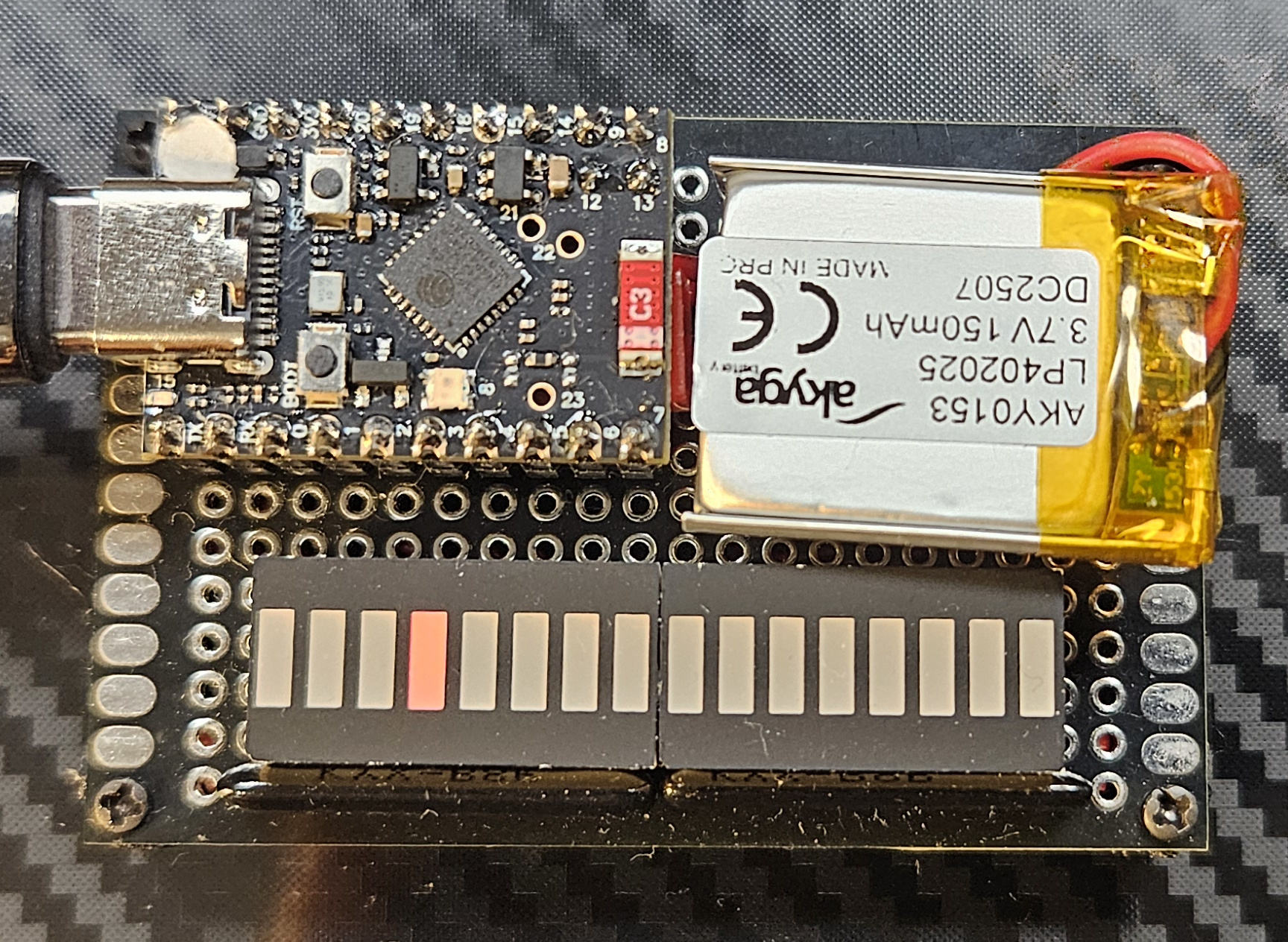
ESP32 C6 super mini
| Cores | ESP32-C6, High Performance Risc-V and Low Power Risc-V, 32 bit |
| Clock | 160 MHz for HP, 20 MHz for LP |
| SRAM | 512K for HP, 16k for LP |
| FLASH | 320K (internal, expandable externally) |
| GPIO | 22 (some not available on a convenient header) |
| Peripherals | 2.4 GHz Wi-Fi 6 (802.11ax), Bluetooth 5 (LE), IEEE 802.15.4 (Zigbee), 3 SPI (two for external flash), 3 UART (one low-power), 2 I2C (one low-power), I2S, RMT, 2 TWAI, SDIO, Motor Control PWM, 7-channel 12-bit ADC, USB 2.0, WDT, 7 timers (various functions) |
| Power draw | 0.1W (not changing the LiPo battery, WiFi & BT powered down), 0.15W (not charging the LiPo, WiFi connected) |
| Other | Built-in core temperature sensor, built-in AES, RSA and HMAC. JTAG debugger support, LiPo battery charger |
Starting with the usual, beefier kind of micro-controller. An ESP32, Risc-V variant (C6) is a beefy, two-core micro-controller with some really impressive specs. It is somewhat well-supported within the usual Arduino-based tools such as, Arduino IDE and Platform IO and is more than capable of driving some LEDs.
The only caveat for this board is the fact that some of the GPIOs available on the headers are used for USB communication, either making it harder to program the board when these pins are used, or having to solder the much less convenient micro-dot pins. I initially went with the former, but that proved to be really annoying. Could be solved by Over-The-Air flashing, but doing that for just this one board seemed excessive. Instead, I just used the remaining well-aligned micro-dot pin instead.
This board implements the RTC HAL routines with NTP, so it doesn't require setting up the time, but does require a WiFi connection to be set up. This will cause the board to boot for a longer time, but the RTC will be used to synchronize the animations with the remaining boards.
Toolchain setup
The toolchain is why I tend to use these boards for everything as a hobbyist. Just initialize a new PlatformIO project, define the environments and you're good to go within 5 minutes:
[env]
framework = arduino
monitor_speed = 115200

[env:esp32c6]
platform = espressif32
board = esp32-c6-super-mini
For this particular chip, the C6, it seems that the PlatformIO Arduino framework from Espressif that's currently pinned upstream does not come configured with any support, so we need to use a different, community-forked platform:
[env:esp32c6]
; Using pioarduino instead of platformio to get support for the C6
platform = https://github.com/pioarduino/platform-espressif32/releases/download/stable/platform-espressif32.zip
board = esp32-c6-super-mini
The super-mini board's configuration itself is also not available, so we need to add that in ./boards/esp32-c6-super-mini.json:
{
  "build": {
    "core": "esp32",
    "f_cpu": "160000000L",
    "f_flash": "80000000L",
    "flash_mode": "qio",
    "mcu": "esp32c6",
    "variant": "esp32c6",
    "extra_flags": [
      "-DARDUINO_ESP32C6_DEV",
      "-DARDUINO_USB_MODE=1",
      "-DARDUINO_USB_CDC_ON_BOOT=1"
    ]
  },
  "connectivity": [
    "wifi",
    "bluetooth"
  ],
  "frameworks": [
    "arduino",
    "espidf"
  ],
  "name": "ESP32-C6 Super Mini",
  "upload": {
    "flash_size": "4MB",
    "maximum_ram_size": 524288,
    "maximum_size": 4194304,
    "require_upload_port": true,
    "speed": 460800
  },
  "url": "https://docs.espressif.com/projects/espressif-esp-dev-kits/en/latest/esp32c6/esp32-c6-devkitc-1/index.html",
  "vendor": "Espressif"
}
And lastly, not to have to define the WiFi SSID nor password in the code we pass that as build params:
[env:esp32c6]
platform = https://github.com/pioarduino/platform-espressif32/releases/download/stable/platform-espressif32.zip
board = esp32-c6-super-mini
build_flags =
    -D HAS_RTC
    -D ESP32_SSID=${sysenv.WIFI_SSID}
    -D ESP32_PASS=${sysenv.WIFI_PASS}
Now, you can pass your pass and ssid via the env variables like this:
export WIFI_SSID='\"your ssid\"'
export WIFI_SSID='\"your pass\"'
pio run -e esp32c6
And these can be accessed in code like so:
const char* ssid = ESP32_SSID;
const char* password = ESP32_PASS;
OK, this wasn't as easy as I remembered. 🤷🏼
HAL implementation
For this platform, the most interesting part is the "RTC" support, or rather, the NTP support:
void initRTC(void) {
  WiFi.mode(WIFI_STA);
  WiFi.begin(ssid, password);

  // ...

  configTime(0, 0, "time.nist.gov", "0.pool.ntp.org", "1.pool.ntp.org");
}
This connects the board to the local WiFi network and sets up several NTP servers kicking off time synchronization for a GMT offset of 0 and daylight savings offset of 0. Fetching the current local time is accomplished like this:
void getRTCTime(struct tm *time) {
  getLocalTime(time);
  time->tm_year = time->tm_year - 100;
}
The year provided this way is the increment from 1900, so 126, but for the animation code to generically support the older platforms (that did not expect history to continue past the year 1999) we need to subtract the 100.
Since the time keeping is done by NTP, we don't support either setting time or toggling the RTC on or off.
void toggleRTC(bool run) {
  // NOTE Nothing to do.
}

void setRTCTime(struct tm *time) {
  // NOTE Nothing to do, NTP handles time synchronization.
}
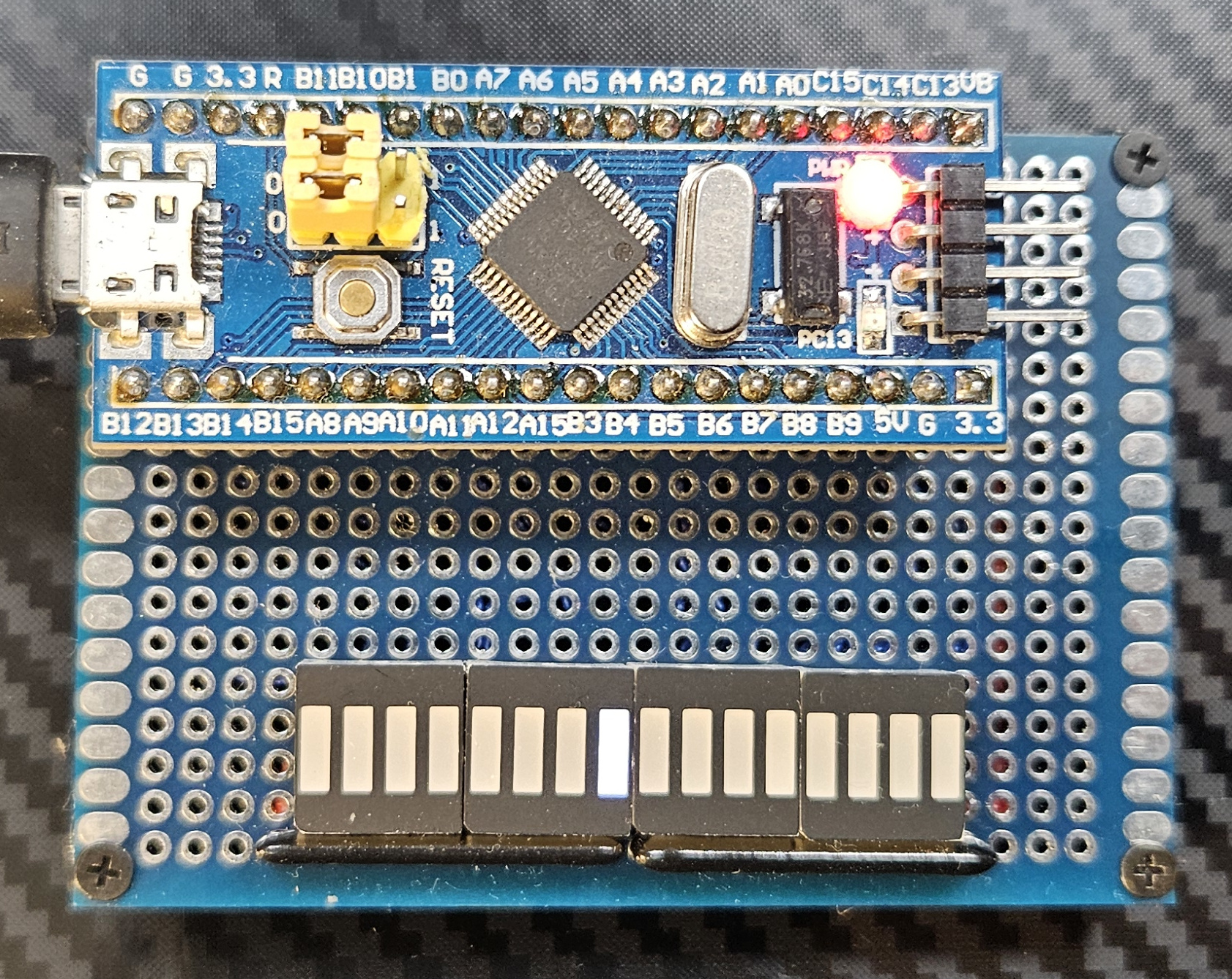
STM32 Bluepill
| Core | STM32F103C8T6, ARM Cortex-M3, 32 bit |
| Clock | 72 MHz |
| SRAM | 20K |
| FLASH | 64K |
| GPIO | 32 I/O (some only 3V3-capable, PA13, PA14 and PA15 with reduced electrical capability) |
| Peripherals | 2 SPI, 2 I2C, 2 10-channel 12-bit ADC, 3 UART, CAN, USB 2.0, 4 timers, RTC |
| Power draw | 0.15W |
| Other | External batery connection for RTC backup, JTAG debugger support |
The Bluepill was my go-to micro-controller module way back when Espressif didn't exist yet. It's got decent resources, communication via USB and convenient JTAG debugging with GDB support and single-stepping. All around very convenient platform with good support from the Arduino & PlatformIO side of things.
Supporting the RTC HAL requires an external battery socket (not pictured).
Toolchain setup
The setup was similar to the ESP32, less complex for sure:
[env:stm32]
platform = ststm32
board = bluepill_f103c8
I tried flashing one of those USB-capable boot-loaders to make flashing easier, but that results in limited debuggability, as you don't immediately have the STLink hooked up to the board, so I reverted back to my "usual" ways. We do want to retain the UART via USB option, hence the need for the extra defines:
[env:stm32]
platform = ststm32
board = bluepill_f103c8
upload_protocol = stlink
In order to support the RTC HAL routines we need to add an external dependency from ST, which somehow is not part of their Arduino port:
[env:stm32]
platform = ststm32
board = bluepill_f103c8
upload_protocol = stlink
build_flags =
    -D HAS_RTC
    -D PIO_FRAMEWORK_ARDUINO_ENABLE_CDC
    -D PIO_FRAMEWORK_ARDUINO_USB_HIGHSPEED_FULL_MODE
    -D USBCON
lib_deps =
    stm32duino/STM32duino RTC
And that's it, we can compile the code with PlatformIO:
pio run -e stm32
HAL implementation
For this platform, again, the RTC setup is the most interesting part:
#include <STM32RTC.h>

STM32RTC& rtc = STM32RTC::getInstance();

void initRTC(void) {
  rtc.setClockSource(STM32RTC::LSE_CLOCK);
  rtc.begin(STM32RTC::HOUR_24);
}
We're setting up the LSE clock (external 32k oscillator) and kick off the RTC, which, given that an external battery is connected to the V_BAT pin, will allow the RTC to keep time even during power-off.
The RTC library that is available for this platform does not support POSIX-style functions, so we need to translate the data format to get a proper struct tm out of the RTC:
void setRTCTime(struct tm *time) {
  rtc.setDate(time->tm_wday, time->tm_mday, time->tm_mon, time->tm_year);
  rtc.setTime(time->tm_hour, time->tm_min, time->tm_sec);
}

void getRTCTime(struct tm *time) {
  uint8_t wday, mday, mon, year, hour, min, sec;
  uint32_t subsec;

  rtc.getDate(&wday, &mday, &mon, &year);
  rtc.getTime(&hour, &min, &sec, &subsec);

  time->tm_wday = wday;
  time->tm_mday = mday;
  time->tm_mon = mon;
  time->tm_year = year;
  time->tm_hour = hour;
  time->tm_min = min;
  time->tm_sec = sec;
}
Even though this RTC supports sub-second resolution, we're ignoring it as it's not immediately useful.
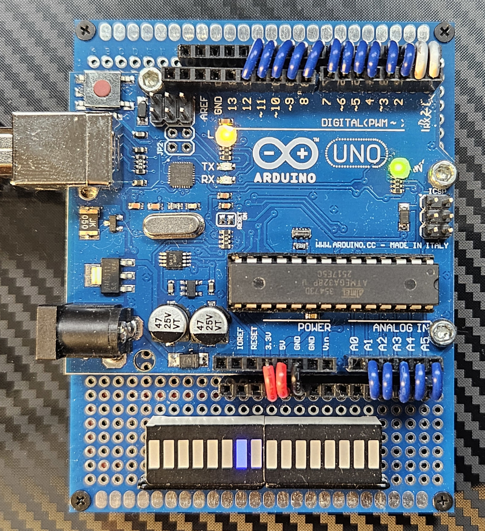
Arduino Uno
| Core | ATmega328p, AVR, 8bit |
| Clock | 16 MHz |
| SRAM | 2k |
| EEPROM | 1k |
| FLASH | 32k |
| GPIO | 23 |
| Peripherals | 2 * SPI, I2C, UART, 8-channel 10-bit ADC, 3 timers (2 8-bit and one 16-bit), WDT |
| Other | On-board serial programmer/debugger based around another ATmega chip. |
| Power draw | 0.15W |
An external I2C DS3231 RTC is supported for this board (not pictured). This required some pin swaps and along with the UART & the LEDs themselves exhausts all available GPIO pins, as the ATmega328p is a fairly limited chip.
I went with a knock-off Arduino board to match the color to proto-board I had. Also, I'm not very keen on supporting Arduino Inc to any extent.
Toolchain setup
The setup this time is actually simple. We just need an external library for the RTC and that's it:
[env:atmega]
platform = atmelavr
board = uno
build_flags =
    -D HAS_RTC
lib_deps =
    adafruit/RTCLib
HAL implementation
Yet again, the RTC is the more interesting bit of the HAL. It's fairly similar to the STM32 version, except the RTC used is an external module, and a different library is driving it:
#include <RTClib.h>

RTC_DS3231 rtc;

void initRTC(void) {
  rtc.begin();
}
This library does not support POSIX-style data formats, so we need to translate:
void setRTCTime(struct tm *time) {
  rtc.adjust(DateTime(time->tm_year, time->tm_mon, time->tm_mday, time->tm_hour, time->tm_min, time->tm_sec));
}

void getRTCTime(struct tm *time) {
  DateTime now = rtc.now();

  time->tm_wday = now.dayOfTheWeek();
  time->tm_mday = now.day();
  time->tm_mon = now.month();
  time->tm_year = now.year() - 2000;
  time->tm_hour = now.hour();
  time->tm_min = now.minute();
  time->tm_sec = now.second();
}
We're also making sure that the output is exactly the same as in the other platform's cases.
Axiom CME11A
| Core | MC68HC11A1FN, M68HC11, 8 bit |
| Clock | 8 MHz |
| SRAM | 8k (external), 512 internal |
| EEPROM | 16k (external), 512 internal |
| GPIO | 11 I/O (Port D, Port A), 11 input only (Port A, Port E) |
| Peripherals | UART (with RS232 port), SCI, SPI, 8-channel 8-bit ADC, 5 timers (16-bit, varying functions), WDT |
| Power draw | 0.5W (9V input) |
| Other | Ports B and C are used for memory bus expansion, board supports up to 32k chips (any mix of EEPROM and SRAM), on-board ootloader and debugger (Bufalo 3.4, occupies 8k of EEPROM), LCD connector, SS keypad connector, expandable memory-mapped peripherals. |
This is where the issues started. This board, despite being really feature-full and driven by a once-well-supported platform is pretty much a nightmare to set up.
Most of the resources that I used to get this board going were found on the late Tony Papadimitriou's GitHub. It appears to me that Tony was the last person singlehandedly keeping the HC11 alive. RIP
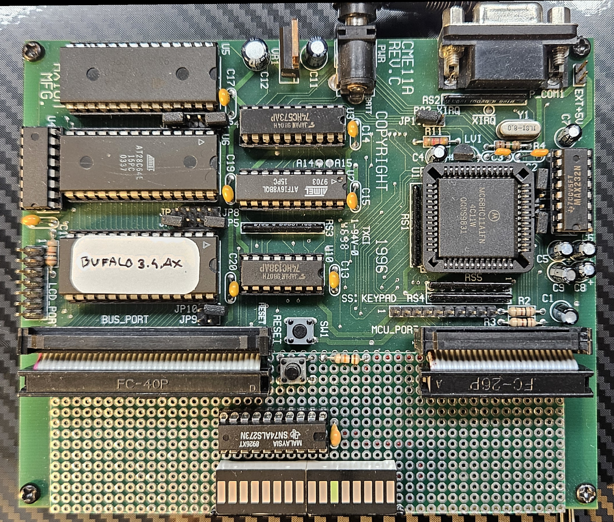
Once set up, though, the board packs quite a few features - it comes pre-flashed with the Buffalo Monitor which allows uploading .s19 dumps directly to RAM, run them, disassemble, change the memory and most importantly - it allows single-step debugging of the code on the board with up to 4 breakpoints! That's 90'ties technology and it proves that Arduino was just timing, not even delivery nor software.
This board is, so far, the only one with no support for the RTC. The MC68HC11 does not come with an RTC, but thanks to the expanded bus mode, one could use an ICM7170-like chip with this board directly. That's possible, but not implemented yet.
Toolchain setup
This board requires an m68hc11 toolchain. Fortunately GNU binutils & GNU GCC at one point supported this platform. Unfortunately, that support seems to no longer be available in the upstream projects, having been removed at around GCC 3.4.6.
We can still fetch the old sources though, so how hard can this be? While we're at it, let's use GEL libc for this platform:
wget https://ftp.gnu.org/gnu/binutils/binutils-2.39.tar.gz
wget https://ftp.gnu.org/gnu/gcc/gcc-3.4.6/gcc-core-3.4.6.tar.gz

# Get GEL from https://sourceforge.net/projects/gel/files/gel-hc1x/1.6.1/gel-hc1x-1.6.1.tar.gz/download
The GCC sources need a patch:
- Patch
config.guessby copying the one from binutils package. - Patch
intl/configureat line 1151 to changemain(){return(0);}toint main(){return(0);} - Patch
libiberty/regex.creplacing the bogus declarations ofchar *malloc();andchar *realloc();at lines 132 and 133 with#include <stdlib.h> - Patch
libiberty/md5.cadding#include <string.h>. - Patch
libiberty/getcwd.creplacingextern char *getwd();on line 33 withextern char *getwd(char*); - Patch
libiberty/getpwd.creplacingextern char *getwd();on line 41 withextern char *getwd(char*); - Patch
libiberty/pex-unix.creplacingextern int execv();on line 47 withextern int execv(const char*, char * const*); - Patch
libiberty/pex-unix.creplacingextern int execvp();on line 48 withextern int execvp(const char*, char * const*); - Patch
libiberty/pex-unix.creplacingint (*func)();on line 59 withint (*func)(const char*, char * const*); - Patch
gcc/collect2.cat line 1537 to add(S_IRUSR|S_IWUSR)as third parameter to open (required with theO_CREATflag, see here for the error you get without patching) - Patch
gcc/config/m68hc11/larith.asmat line 97 to read.space 2instead of.dc.w 1(to reserve uninitialized space for the virtual regs) - Patch
gcc/cpplib.creplacingU"#";on line 194 with(const uchar*)U"#" - Patch
gcc/cpplib.creplacingU"pragma dependency";on line 659 with(const uchar*)U"pragma dependency" - Patch
gcc/cpplex.cadding(const uchar*)before everyU-prefixed string on line 42 - Patch
gcc/cpplex.cadding(const uchar*)before everyU-prefixed string on line 42 - Patch
gcc/cppmacro.cadding(const uchar*)beforeU-prefixed strings on lines 223 and 224 - Patch
gcc/insn-output.caddingextern int m68hc11_is_far_symbol (rtx);at the top. - Patch
gcc/insn-output.caddingextern int m68hc11_is_trap_symbol (rtx);at the top.
As a convenience, there is a patch file in the repo: hc11/gcc.patch
The GEL sources also need patching:
- Changing the
m6811-elf-binutils prefix tom68hc11-elf-where appropriate. - Removing any
.ccfiles from the makefiles as C++ is not supported.
As a convenience, there is a patch file in the repo: hc11/gel.patch
Here's the full script to get a toolchain going:
cd hc11
mkdir -p build/bin
export PATH=$PATH:`pwd`/build/bin

# Binutils
tar zxvf binutils-2.39.tar.gz
mv binutils-2.39 binutils-m68hc11-elf-2.39
cd binutils-m68hc11-elf-2.39
./configure --prefix=`pwd`/../build --target=m68hc11-elf
make
make install

cd ..

# GCC
tar zxvf gcc-core-3.4.6.tar.gz

# Patch the sources!
patch -s -p0 < gcc.patch

mv gcc-3.4.6 gcc-m68hc11-elf-3.4.6
cd gcc-m68hc11-elf-3.4.6
./configure --prefix=`pwd`/../build --target=m68hc11-elf
make
make install

cd ..

# GEL LibC
tar zxvf gel-hc1x-1.6.1.tar.gz

# Patch the sources!
patch -s -p0 < gel.patch

cd gel-hc1x-1.6.1

make TARGET_BOARD=m68hc11-cme11

cd ..
mkdir -p build/lib
mkdir -p build/include
cp -r gel-hc1x-1.6.1/lib/* build/lib
cp -r gel-hc1x-1.6.1/include/* build/include
This will create all the necessary binaries in hc11/build/bin and libraries in hc11/build/lib and hc11/build/include. Building the project with the above in place is then a matter of:
make cme11a-clean && make cme11a
truncate --size=8k firmware/cme11a.bin
Flashing the firmware
The project can be uploaded to a CME11-type board via serial and hc11/upload.py script. You may need to upgrade the U5 RAM chip to 32k to fit the sketch, unless your board already came with that option.
Alternatively, you can update the memory map to point the text section to U6 EPROM space and burn it into a ROM chip. You will need to update the reset vector in Buffalo EPROM U7 to point to 0x8000 for the program to start automatically.
Bootloader mods
If you want to retain the interactive debugging boot-loader, a modified Buffalo monitor is provided in hc11/buf341.asm. In can be compiled with asm11 and burned to the U7 ROM chip. It's not exactly the same as the version on the board, but the functionality is complete. The modification causes Buffalo to jump to 0x8000 when pin 0 of PORTE is high at boot.
A modified version of the original Axiom Buffalo 3.4AX ROM is available in hc11/buf34ax.bin and a modified version that allows running ROM code in hc11/buf341ax.bin. This was modified by hand using the hc11/bufpatch.asm
The Buffalo Monitor sources come from this repository.
HAL implementation
This one was a lot more elaborate even though there's a libC available for this platform...
First of all, the MCU on this board does not expose enough GPIO pins to make the LED bar work, so an external register was added to the MCU bus under the address of 0xb580.
#define PX0 0x40
#define PX1 0x41
#define PX2 0x42
#define PX3 0x43
#define PX4 0x44
#define PX5 0x45
#define PX6 0x46
#define PX7 0x47

#define PORTX ((uint8_t*) 0xb580)

volatile uint8_t PX_VALUE = 0x00;

void digitalWrite(uint8_t pin, uint8_t value) {
  uint8_t off = pin & 0xf;
  uint8_t mask = 1 << off;

  // A and D ports handled here...

  if (pin >= PX0 && pin <= PX7) {
    PX_VALUE = (value == LOW) ? (PX_VALUE & ~mask) : (PX_VALUE | mask);
    *PORTX = PX_VALUE;
  }
}
Since it's just a memory location, we can just write to that location to get the LED bar to display the value. That register is, of course, write-only, so there's no way to set pinMode for any of those pins. Furthermore, it only supports whole-register writes, so we need to maintain the current value in-memory, so that we can change individual pin values without affecting the other pins of the register.
For the remaining LEDs in the LED bar a mix of port A and port D pins is used:
#define PA0 0x00
#define PA1 0x01
#define PA2 0x02
#define PA3 0x03
#define PA4 0x04
#define PA5 0x05
#define PA6 0x06
#define PA7 0x07

#define PD0 0x30
#define PD1 0x31
#define PD2 0x32
#define PD3 0x33
#define PD4 0x34
#define PD5 0x35
#define PD6 0x36
#define PD7 0x37

volatile uint8_t PA_VALUE = 0x00;
volatile uint8_t PD_VALUE = 0x00;

void digitalWrite(uint8_t pin, uint8_t value) {
  uint8_t off = pin & 0xf;
  uint8_t mask = 1 << off;

  if (pin >= PA0 && pin <= PA7) {
    PA_VALUE = (value == LOW) ? (PA_VALUE & ~mask) : (PA_VALUE | mask);
    _io_ports[M6811_PORTA] = PA_VALUE;
  } else if (pin >= PD2 && pin <= PD5) {
    PD_VALUE = (value == LOW) ? (PD_VALUE & ~mask) : (PD_VALUE | mask);
    PD_UART = _io_ports[M6811_PORTD] & 0x03;
    _io_ports[M6811_PORTD] = PD_UART | PD_VALUE;
  }

  // Port X handle here ...
}
Here, similarly, we can only write whole-byte values to these ports, meaning we have to maintain the current value and update individual pins this way. Port D is especially tricky as it is also used for the UART communication - each time we perform a whole-byte write of the port, we first fetch the values of PD0 and PD1, to make sure we don't change these mid-transfer. I'm pretty sure it's not the right way to do this, but I can't argue with the results (I didn't check if it actually works, so I'm not arguing here 🤷🏼). Lastly, only some of the pins in ports A and D are bi-directional, so pinMode needs to take that into account:
void pinMode(uint8_t pin, uint8_t mode) {
  uint8_t off = pin & 0xf;
  uint8_t mask = 1 << off;

  if (pin == PA7) {
    uint8_t curr = _io_ports[M6811_PACTL];
    _io_ports[M6811_PACTL] = (mode == OUTPUT) ? (curr | mask) : (curr & ~mask);
  }  else if (pin >= PD2 && pin <= PD5) {
    uint8_t curr = _io_ports[M6811_DDRD];
    _io_ports[M6811_DDRD] = (mode == OUTPUT) ? (curr | mask) : (curr & ~mask);
  }
}
Another interesting aspect of this HAL is the timer interrupt. We want to be able to count how many milliseconds have passed and do that accurately enough. That can be achieved, well, by using timer interrupts built into the MCU:
set_interrupt_handler(RTI_VECTOR, timer_interrupt);
timer_initialize_rate(M6811_TPR_16);
The above code sets a timer interrupt vector and sets the timer prescaler to a sane value that will allow us to count the timer ticks:
volatile uint64_t __currTicks = 0;

void __attribute__((interrupt)) timer_interrupt (void) {
  __currTicks++;
  timer_acknowledge();
}
This generates a timer interrupt roughly every 4.096 milliseconds, so we can compute the current milliseconds since boot time as follows:
uint64_t currMillis(void) {
  lock();
  uint64_t v = __currTicks;
  unlock();

  return v * 4;
}
The issue becomes apparent after a few minutes - the clock drifts wildly since every 4 milliseconds we're discarding about 0.1 milliseconds of time that passed. That's annoying, but it can be made to work two ways:
// Option 1:
return v * 1000L / (M6811_CPU_E_CLOCK / TIMER_DIV);

// Option 2:
return v * 4; // ???
Option 1 is to properly compute the number of milliseconds that have passed since our interrupt routine was called the last time, but that has a somewhat surprising side effect. The MCU on this board, the MC68HC11, does not have any hardware division logic, meaning that any division must be emulated in software. That's done under the hood for us by GCC, even for 64-bit numbers. That code, however, is truly massive - the division alone inflates the ROM binary by 6 kilobytes, which is funny considering that we have about 8 kilobytes of space available for the entire firmware.
Option 2 is to remain using a simple conversion, but fudge the ticks count so that it works out in the end:
volatile uint64_t __currTicks = 0;
volatile uint8_t __currTicksAdjust0 = 0;
volatile uint8_t __currTicksAdjust1 = 0;

void __attribute__((interrupt)) timer_interrupt (void) {
  __currTicks++;
  __currTicksAdjust0++;
  __currTicksAdjust1++;

  if (__currTicksAdjust0 == 40) {
    __currTicksAdjust0 = 0;
    __currTicks++;
  }

  if (__currTicksAdjust1 == 250) {
    __currTicksAdjust1 = 0;
    __currTicks--;
  }

  timer_acknowledge();
}
Here we increment the ticks counter as previously, but we also maintain two extra counters used for the count adjustments:
- Every 40 ticks we add an extra one (that's as if there were 4.1 milliseconds for each tick on average), but that creates an overshoot...
- ...so we decrement the counter every 250 ticks, so that on average each tick represents about 4.096 milliseconds.
This way we can keep the time somewhat accurately without having to perform space-inefficient computations.
Lastly, since there is no Arduino framework present, we need to provide the main entry point:
int main(void) {
  initSerial();
  initTimer();

  setup();

  for(;;) {
    loop();
  }

  return 0;
}
No surprises here, we initialize the serial & timers, then call the setup() and loop() functions. No more setup is needed as it's already performed by the Buffalo bootloader for us.
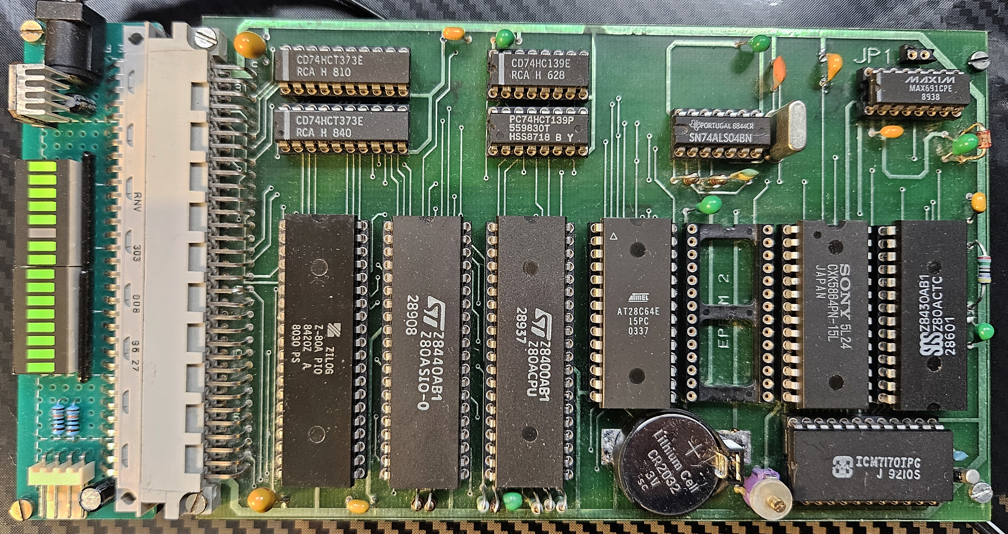
Temex CPU card
| Core | Z80, 8 bit |
| Clock | 2.4576 MHz |
| SRAM | 8k |
| EEPROM | 8k |
| GPIO | 16 I/O via Z80 PIO, 16 input only via memory mapped registers. |
| Peripherals | 2 * UART (Z80 SIO), RTC (ICM7170IPG), 4 Timers (Z80 CTC), WDT (MAX691CPE). |
| Power draw | 2.5W (9V input) |
| Other | SRAM & RTC battery backup (MAX691CPE), second EEPROM slot (max 8k). |
As far as I can tell this once was used as a serial to parallel adapter of some sorts - receiving commands via the UART and then, depending on the command, setting the parallel ports to some specific values and polling for data.
More on the card, including its reverse-engineering here.
Some caveats with this board:
- Most of the chips on the board had to be replaced due to all kinds of weird failures - the original chips include the CPU, SIO, MAX691CPE and the misc 74XX logic.
- The CPU reset line (from MAX691CPE) had a massive capacitor on it, causing erratic boot up behaviour. Had to be replaced with a smaller value.
- Neither EEPROM nor RAM slots utilize the top two JEDEC-pinout address lines, meaning that no more than 8k of memory is addressable in each slot, despite the memory mapping allowing for 16k addresses. The board can be modified to support 32k ROM and 16 RAM (although, all slots need to be populated with 32k chips).
- The RTC only worked during power-up, not supporting backup operation at all.
RTC mods
There were multiple issues with the RTC circuit on this board:- RTC/NVRAM battery was not present, not sure what type should be used.
- RTC oscillator circuit is hooked up to the main 5V line, meaning that when there's no power, it does not oscillate. Very real time, much convenient.
- RTC chip requires pull-ups on
RD&WRlines during external backup. These were not present on the board preventing the chip from counting time during backup.
The battery was the easy one - with a 32k crystal, the RTC chip (ICM7170) supports backup operation down to 1.8 Volts, so a run-of-the-mill CR2032 was a good choice.
The latter two issues were a bit of a head scratcher. It took a careful reading of the data-sheet to determine that the circuit on-board is ill-suited for power-down time keeping (which, honestly, defeats the purpose of having a backup battery hooked up to the chip in the first place). The circuit did not use the ICM7170 built-in power-down detector and instead supplied an external MAX691-based alternative instead. The caveat is that the oscillator circuit relied heavily on the 5V line to be present for operation, and on top of that the chip would not be put down to low-power mode, because the chip-select line was driven low during backup power operation.
To make matters worse, so were the read & write lines with the addresses and data lines floating, meaning that the chip could perform erroneous reads and writes with arbitrary data when on backup power.
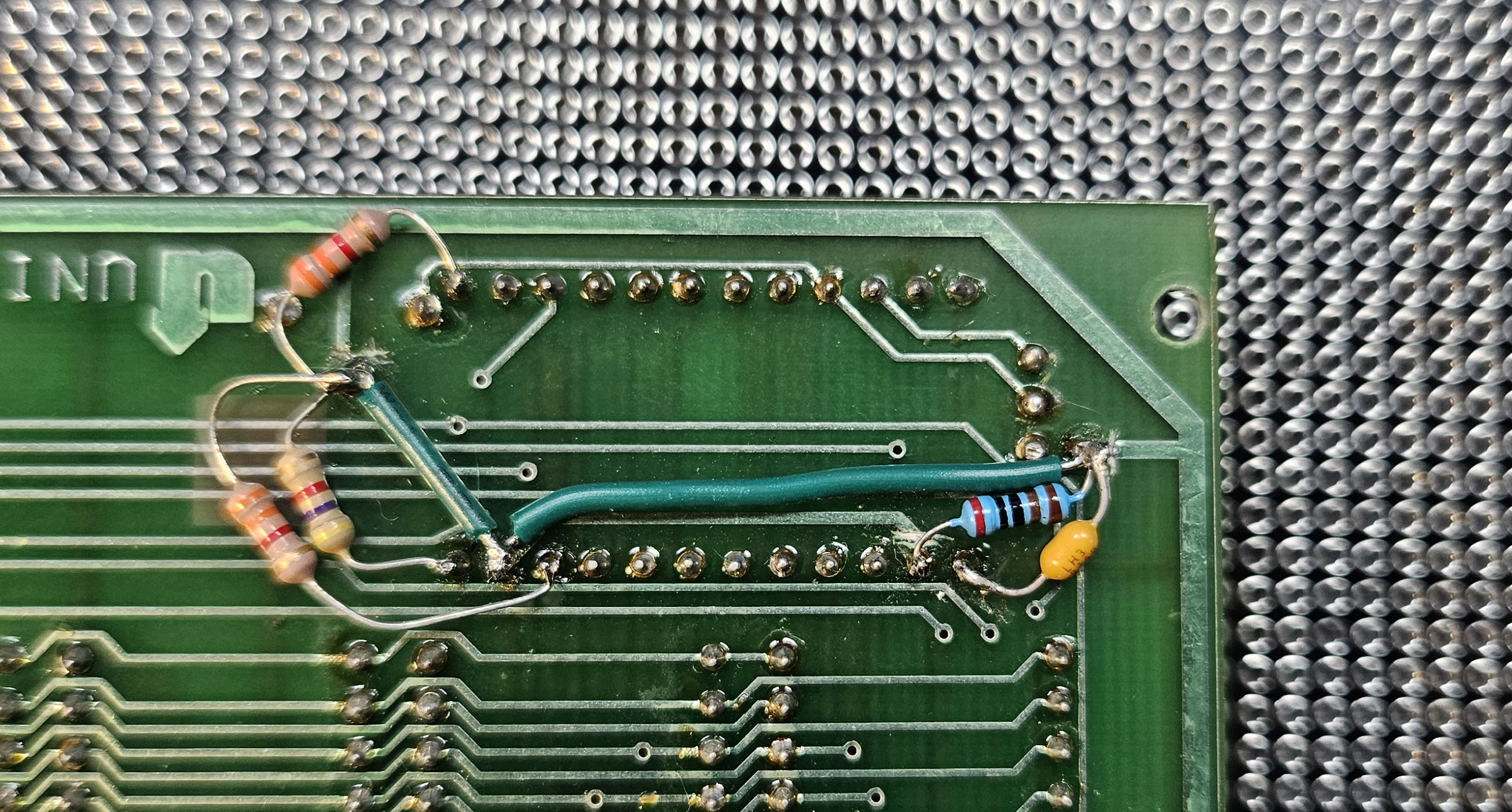
All that resulted is the RTC not keeping its time during power-down and had to be addressed by a hardware mod:
It's not pretty, but it works. First step was to cut the oscillator pull-ups to the 5V line and replace these with a wire going to the backup voltage.
Next, I added pull-ups for the RD, WR and CS lines. CS and RD were particularly power-hungry, so I had to go with 2.2k instead of the more appropriate 4.7k. Battery life will probably suffer.
Lastly, I took the pedantic option and added the 2k resistor between the backup power and the V_BACKUP pin, as mandated by the data-sheet. While at it, I also added a bypass capacitor, though the placement of that leaves something to be desired...
I didn't bother pulling the data & address lines high as the chip is now properly disabled during power-down. As per the data-sheet, that can affect the battery life as some stray currents may still flow with the data lines floating.
Toolchain setup
This board requires SDCC & related binutils. Tested under the following version:
SDCC : mcs51/z80/z180/r2k/r2ka/r3ka/sm83/tlcs90/ez80_z80/z80n/r800/ds390/pic16/pic14/TININative/ds400/hc08/s08/stm8/pdk13/pdk14/pdk15/mos6502/mos65c02/f8 4.5.0 #15242 (Linux)
SDCC has a very small built-in library available, but it's intentionally kept generic and small. As a generic Z80 libc does not seem to exist a lot of this code needed to be written from scratch for this board, including the C runtime bootstrap, interrupt vector tables handling and IO handling. I thin this was my favorite part of this whole project, rarely do you ever get this close to the hardware anymore.
SDCC does not support C++ code, nor even files with a .cpp extension so some trickery was used in the Makefile:
main.rel: src/main.cpp
	@cp $^ /tmp/main.c
	$(CC) $(CFLAGS) -o $@ -c /tmp/main.c
Yup, we just rename main.cpp and hope it works. It does, but that limits what language features we can use in C++. Building the project is now a mater of:
make -f Makefile.z80
Flash the ROM chip in EEPROM1 position.
HAL implementation
C runtime
This platform was the most elaborate so far. There's a very limited standard library available in SDCC, but there's quite literally zilch in it. Everything needed to be implemented from scratch for this specific setup, including the C runtime bootstrap:.module crt0
;; Reset vector
.org 0
jp init
;; Init
.org 0x70
init:
ld sp, #0x8200 ;; Set up stack pointer
call ___sdcc_external_startup
or a, a
call Z, gsinit ;; Initialise global variables
call _main
halt
The reset vector is set to jump to the init function that performs the C runtime initialization and then calls the user-defined main() function. The other vectors are more interesting...
The Z80 processor supports several ways of triggering small sections of code stored at a few initial offsets in the ROM. Whenever the NMI pin of the processor is pulled low, it'll suspend execution of the current instruction and jump to the interrupt vector stored in memory at offset 0x66. Similarly, when an interrupt INT pin is pulled low and the Z80 processor is in the interrupt mode 1, the processor will jump to the interrupt vector at offset 0x38. Interrupts can also be triggered by specific RST XXXX instructions causing the execution to jump to a specific interrupt vector named by the instruction, including: 0x08, 0x10, 0x18, ..., 0x38.
This is somewhat inconvenient as these interrupt vectors are static - these need to be burned into the ROM and can't be change during runtime... Unless some trickery is in place:
.org 0x08
push hl
ld   hl, (#0x8000)
ex   (sp), hl
ret

.org 0x10
push hl
ld   hl, (#0x8002)
ex   (sp), hl
ret

.org 0x18
push hl
ld   hl, (#0x8004)
ex   (sp), hl
ret

.org 0x20
push hl
ld   hl, (#0x8006)
ex   (sp), hl
ret

.org 0x28
push hl
ld   hl, (#0x8008)
ex   (sp), hl
ret

.org 0x30
push hl
ld   hl, (#0x800a)
ex   (sp), hl
ret

.org 0x38
push hl
ld   hl, (#0x800c)
ex   (sp), hl
ret

;; NMI reset vector
.org 0x66
push hl
ld   hl, (#0x8018)
ex   (sp), hl
ret
The trickery here is that we're making the interrupt service routines present at the expected offsets to fudge up the stack return address to point to an interrupt vector table stored in RAM at address 0x8000 (start of RAM for this board). To achieve that, the hl register is first pushed to the stack. That's a 16-bit register, which is the same width as the native pointer type. Next, we load hl with the address of an entry stored in the RAM vector table and then perform an exchange of the value stored at the top of the stack with hl. This way what we end up with is an address of the actual interrupt service routine stored on the top of the stack and a set of registers exactly the same as when we started executing the interrupt handler. The only remaining thing to do is to somehow jump to the code pointed to by the top of the stack, that is, return to it. Note that the ret instruction is not the correct way to return from an interrupt. That should either be done by reti or retn (for non-maskable interrupts). This ret in the code is used as a jump and the interrupt service routine present at that location is expected to properly return.
This trick allows us to rebind the handlers in that interrupt vector table at runtime:
void isrTrap(void)  __critical __interrupt(0) {
  __asm__("halt");
}

void nmiTrap(void) __critical __interrupt {
  __asm__("halt");
}

void* __at(0x8000) RESET_VECTORS[13] = {
  isrTrap, // RST 8
  isrTrap, // RST 10
  isrTrap, // RST 18
  isrTrap, // RST 20
  isrTrap, // RST 28
  isrTrap, // RST 30
  isrTrap, // RST 38
  (void*) 0x00,
  (void*) 0x00,
  (void*) 0x00,
  (void*) 0x00,
  (void*) 0x00,
  nmiTrap // RST 66
};

void setResetVector(uint8_t offset, void* vector) {
  RESET_VECTORS[offset>>3] = vector;
}

void *getResetVector(uint8_t offset) {
  return RESET_VECTORS[offset>>3];
}
Now, whenever a reset condition or an non-maskable interrupt is triggered, the CPU will run those service routine stubs and jump to the actual interrupt service routines stored in the RAM table.
Timers & time
The board is using a Z80 CTC chip for all timer handling. The chip is mapped at offset 0x00 in the IO space:
__sfr __at(0x00) CTC_C0;
__sfr __at(0x01) CTC_C1;
__sfr __at(0x02) CTC_C2;
__sfr __at(0x03) CTC_C3;
The firmware is using CTC timer 3 for the main millisecond count. The input clock to this timer is the system clock of 2.4576 MHz, which is very convenient, since we can just divide that down by 16 (CTC prescaler) and then 154 (time constant) to obtain something close-enough to a millisecond. Then the interrupt handler for this timer becomes just:
volatile uint64_t __currMillis = 0;

void ctcC3Timer(void) __critical __interrupt(3) {
  __currMillis++;
}

uint64_t currMillis(void) {
  // NOTE Needed for atomic access.
  __asm__("di");
  uint64_t value = __currMillis;
  __asm__("ei");
  return value;
}
The accuracy of this clock depends heavily on the accuracy of the crystal oscillator (which isn't high), so that's going to have some drift. Fortunately, the board comes with an RTC clock on-board:
__sfr __at(0xc0) RTC_C_HSEC;
__sfr __at(0xc1) RTC_C_H;
__sfr __at(0xc2) RTC_C_M;
__sfr __at(0xc3) RTC_C_S;
__sfr __at(0xc4) RTC_C_MO;
__sfr __at(0xc5) RTC_C_D;
__sfr __at(0xc6) RTC_C_Y;
__sfr __at(0xc7) RTC_C_DOW;
__sfr __at(0xc8) RTC_R_HSEC;
__sfr __at(0xc9) RTC_R_H;
__sfr __at(0xca) RTC_R_M;
__sfr __at(0xcb) RTC_R_S;
__sfr __at(0xcc) RTC_R_MO;
__sfr __at(0xcd) RTC_R_D;
__sfr __at(0xce) RTC_R_Y;
__sfr __at(0xcf) RTC_R_DOW;
__sfr __at(0xd0) RTC_INT;
__sfr __at(0xd1) RTC_CTRL;
This chip, the ICM7170 is mapped at offset 0xc0 of the IO space and is fairly straightforward to use (assuming the circuit it's a part of is properly terminating its signals, etc):
void initRTCInt() {
  RTC_INT = 0x00;

  uint8_t curr = RTC_CTRL;
  RTC_CTRL = curr & ~0x10; // Disable interrupts.
}

void setRTCTime(struct tm *t) {
  RTC_C_HSEC = t->tm_hundredth;
  RTC_C_S = t->tm_sec;
  RTC_C_M = t->tm_min;
  RTC_C_H = t->tm_hour;
  RTC_C_D = t->tm_mday;
  RTC_C_MO = t->tm_mon;
  RTC_C_Y = t->tm_year;
  RTC_C_DOW = t->tm_wday;
}

void getRTCTime(struct tm *t) {
  t->tm_hundredth = RTC_C_HSEC;
  t->tm_sec = RTC_C_S;
  t->tm_min = RTC_C_M;
  t->tm_hour = RTC_C_H;
  t->tm_mday = RTC_C_D;
  t->tm_mon = RTC_C_MO;
  t->tm_year = RTC_C_Y;
  t->tm_wday = RTC_C_DOW;
}
The catch here is the fact that this chip does not support vectorized interrupts, meaning whenever in triggers the interrupt line, it does not present an interrupt offset on the data bus and instead it is the CPU's responsibility to poll the chip to check if it was responsible for the interrupt, and what exactly caused it. We're just ignoring interrupts here altogether and we'll be polling the chip for time data explicitly.
Console IO
The serial console is done with a Z80 SIO/0 chip mapped at offset 0x40 in the IO space:
__sfr __at(0x40) SIO_DATA_A;
__sfr __at(0x41) SIO_DATA_B;
__sfr __at(0x42) SIO_CTRL_A;
__sfr __at(0x43) SIO_CTRL_B;
There are two UARTs in total, but the firmware makes use of only one of these - the A side. The setup is a bit elaborate:
void enableARX(void) {
  SIO_CTRL_A = 0x03; // Select WR3
  SIO_CTRL_A = 0xc1; // RX 8 bit, auto enable off, RX on
}

void enableARTS(void) {
  SIO_CTRL_A = 0x05; // Select WR5
  SIO_CTRL_A = 0xea; // DTR on, break off, TX 8 bit, TX on, RTS on
}

void initSIO(int8_t interrupts) {
  SIO_CTRL_A = 0x30; // Error reset.
  SIO_CTRL_A = 0x18; // Reset & abort

  SIO_CTRL_A = 0x04; // Select WR4
  SIO_CTRL_A = 0x44; // CLK x16, 1 stop bit, no parity

  enableARTS();

  if(interrupts == -1) {
    SIO_CTRL_A = 0x01; // Select WR1
    SIO_CTRL_A = 0x00; // Disable interrupts
  } else {
    SIO_CTRL_B = 0x01; // Select WR1
    SIO_CTRL_B = 0x04; // No interrupt in channel B, special RX condition affects vector

    SIO_CTRL_B = 0x02; // Select WR2
    SIO_CTRL_B = 0x00; // Set up the interrupt vector

    SIO_CTRL_A = 0x01; // Select WR1
    SIO_CTRL_A = 0x18; // Interrupt on all RX characters, buffer overrun is a special RX condition, parity is not
  }

  enableARX();
}
The RX and TX clocks are connected to the CTC timer outputs, so we set up the CTC first and then initialize the SIO assuming a stable clock. The setup enables vectored interrupts and configures the widely supported 8N1 at roughly 9600 baud.
To send something to the serial console:
void flushATX(void) {
  bool flushed = false;

  do {
      SIO_CTRL_A = 0x01; // SELECT RR1
      uint8_t b = SIO_CTRL_A;

      if (b & 0x01) {
        flushed = true;
      }
  } while (!flushed);
}

int putchar(int c) {
  SIO_DATA_A = c & 0xff;
  flushATX();
  return 0;
}

void display(const char* s) {
  const char *i = s;
  while (*i != '\0') {
    putchar(*i);
    i++;
  }
}
This isn't ideal, as it create a visible delay in the LED bar whenever a lengthier log is printed. A better way to handle the TX flushing would be to introduce double buffering and configure transmit interrupts.
GPIO
The GPIO is handled by the Z80 PIO, mapped at offset 0x80 in the IO space:
__sfr __at(0x80) PIO_DATA_A;
__sfr __at(0x81) PIO_DATA_B;
__sfr __at(0x82) PIO_CTRL_A;
__sfr __at(0x83) PIO_CTRL_B;

#define PORTA ((void *) 0x80)
#define PORTB ((void *) 0x81)

volatile uint8_t PIO_VALUE_A = 0x00;
volatile uint8_t PIO_VALUE_B = 0x00;

void writePort(void* port, uint8_t value) {
  if (port == PORTA) {
    PIO_VALUE_A = value;
    PIO_DATA_A = value;
  } else if (port == PORTB) {
    PIO_VALUE_B = value;
    PIO_DATA_B = value;
  } else {
    // Not supported.
    __asm__("rst 0x8");
  }
}

uint8_t readPort(void* port) {
  if (port == PORTA) {
    return PIO_DATA_A;
  } else if (port == PORTB) {
    return PIO_DATA_B;
  } else {
    return *((uint8_t*)port);
  }
}
The PIO only supports whole-byte direction changes and writes, so we need to maintain the current values for both ports in memory. This also complicates the pinMode implementation slightly.
Main
Putting it all together into a main function:
int main(void) {
  setInterruptVector(0, ISR(0));
  // ...
  setInterruptVector(32, ISR(32));

  setInterruptVector(0x16, ctcC3Timer);
  setInterruptVector(0x0c, sioARXByteAvailable);
  setInterruptVector(0x0e, sioARXByteCondition);

  initCTC3(154, 0x10); // Interrupt every 1 ms.
  initSerial();
  initPIOA(PIO_INPUT); // Input
  initPIOB(PIO_INPUT); // Input
  initPortsCD();
  initRTCInt(false, 0x00);

  initInterrupts();

  setup();

  for(;;) {
    loop();
  }
}
There is quite a bit of setup here, starting with the interrupt vectors, the various peripheral devices and lastly, actually enabling the interrupts in z80 mode 2. Since the board technically supports non-volatile RAM, we can make use of that by returning a 0 value from the __sdcc_external_startup() function. We do need to verify that the setup was actually done at some previous point though:
unsigned char __sdcc_external_startup(void) {
  if (getInterruptVector(0x16) == ctcC3Timer
      && getInterruptVector(0x0c) == sioARXByteAvailable
      && getInterruptVector(0x0e) == sioARXByteCondition) {
    // Setup is correct, skip initializing RAM.
    return 1;
  } else {
    // Setup stuff that needs to be set up just once.
    return 0;
  }
}
The interrupt table is a pretty decent place to look for that verification - if the RAM kept its contents, then we expect to find specific function pointers at specific offsets of the RAM interrupt vector table. If that is the case, we can skip the global variable initialization (that would otherwise overwrite the interrupt table and the values stored in the other global variables).
2026-01-06: Added more details on each platforms' HAL implementation.